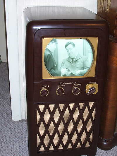
Restoring The Admiral Model 20X1 B/W Television Set

Trade Name: Admiral
Manufacturer: Admiral Corporation Chicago, Ill.
Model Year: 1949
Type Set: Television Receiver B/W
Tubes: Nineteen
Picture: 10-inch Black & White
Tuning Range: Channels 2 thru 13
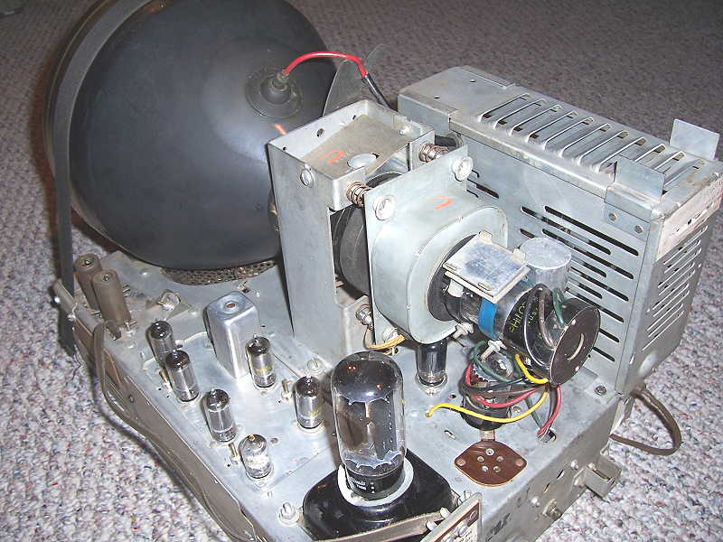
Cabinet: Bakelite Console - BrownThe chassis is transformer powered utilizing a 19 tube line-up. Electro-magnetic deflection is used on the picture tube. The speaker is of the electro-dynamic type with the field coil used as one of the two filter chokes in the LV power supply. The tuner is of the turret type.
Tube Line-up:
V1 6AG5.....1st RF Amp V11 6AS5.....Audio Output V2 6J6......Mixer/Osc V12 12AU7.....Sync Amp-Sync Sep V3 6AU6.....1st Video I-F V13 12AU7.....Vert Osc-Vert Amp V4 6AU6.....2st Video I-F V14 6SN7......Horiz AFC-Horiz Osc V5 6AU6.....3nd Video I-F V15 6BG6......Horiz Output V6 6AL5.....Video Det.-AGC V16 5W4.......Damper V7 6AU6.....Video Amp V17 1X2.......HV Rectifier V8 6AU6.....Sound I-F V18 5U4.......LV Rectifier V9 6AL5.....Ratio Detector V19 10BP4.....Picture Tube V10 6SN7.....AF Amp/Sync Clipper
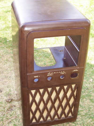
The unit is housed in a Brown Bakelite cabinet measuring 32 1/4 inches high, 16 1/4 inches wide, and 17 inches deep. I can't vouch for any truth in it, but I have been told that this is the largest piece of Bakelite ever cast.
Click thumbnail for larger picture.
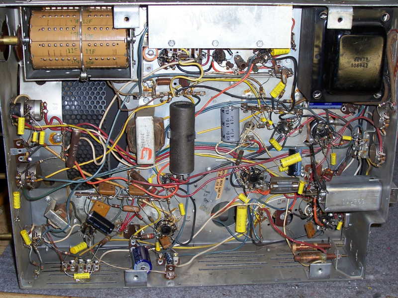
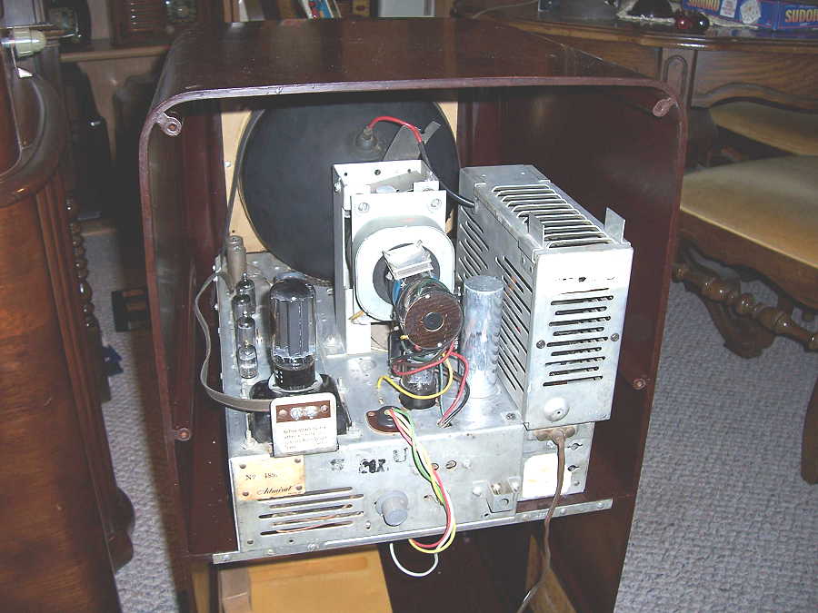
The chassis was dusty but no corrosion or rust. A quick going over with the air compressor and brush removed most of dust and a close inspection showed things to be in very good shape.
Click thumbnail for larger image.
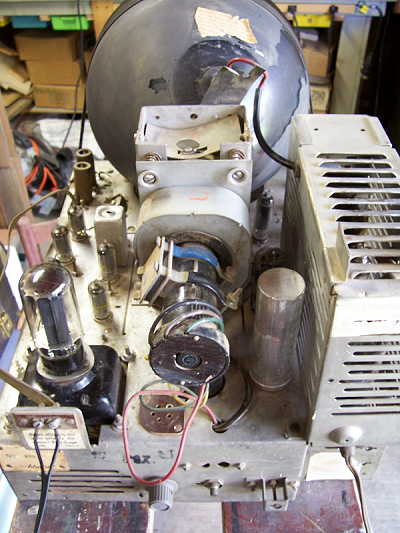
A query on one of the antique radio forums yielded the promise of a schematic. Meanwhile, I looked over the chassis being mindful of the burnt smell, but finding nothing unusual I decided to bring it up on the variac to see if it would show any signs of life. All of the tube filaments lit up except for the 5U4 rectifier. I pulled the 5U4 rectifier tube and discovered that the key-way had been broken off and the it had been incorrectly inserted in the tube socket. After inserting the tube correctly still no signs of life, that is when I discoverd that the speaker field coil was open, thus no B plus voltage. I substuted a choke in place of the field coil, temporarly connected a PM speaker and the set showed promise with sound but no raster.
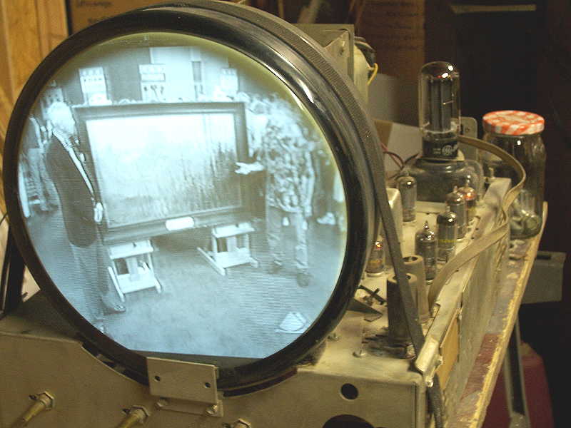
Bringing the tip of a screwdriver blade close to the top cap of the 6BG6 horizontal output tube should produce a voltage arc if the horizontal circuit is working, but no arc was observed. Without the horizontal oscillator circuit working, there would be no high voltage on the picture tube. A look under the chassis revealed a blown fuse in the horizontal output circuit. Replacement of the fuse resulted in HV but still no raster. Hmmm...do I have a picture tube with no emission? Then I spied the ion trap on the neck of the tube and with a little adjustment the tube sprang to life with a nice bright raster.
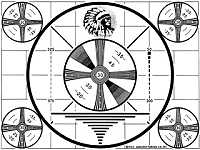
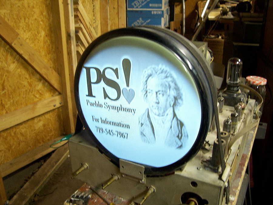
With rabbit ears attached, a few adjustments and the set received the three local stations with quite a good picture.
Click thumbnail for larger image
While waiting for the schematic to arrive via U.S. mail, I decided to proceede ahead and replaced all of the electrolytic and paper capacitors.
Click thumbnail for larger image.
The schematic arrived so time to check voltages against the readings in the voltage chart. All voltages check out well within tolerance so now to hook up the generator and oscilloscope and do a bit of alignment. Since the set is playing so well I suspect that only a touch up will be necessary. Going through the alignment procedures proved that to be the case and a slight improvement was noticed, especially with the tuning of the audio.
This set uses inter-carrier audio instead of split sound audio. The TV signal carries both the video and audio signals. At some point the audio and video must be separated and detected separately. In split sound, the audio portion of the signal is taken off just before the video Intermediate Frequency amplifier chain where it is amplified and detected in the audio IF stages. In inter-carrier audio, the audio signal is amplified along with the video signal in the video IF circuit, the sound being pulled off at the end of the video IF chain. This eliminates a stage or two of separate sound amplification, saving on tube and component count.
A good going over of the chassis with a damp rag, a few Q-Tips and the chassis came out looking quite clean.
Click thumbnail for larger image.
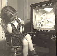
Finally the problem of the open field coil had to be resolved. I began removing the outer layers of insulation around the coil and discovered that the connection between one of the external wires and the small field coil wire was broken where they were orginally joined. This was resoldered and the outer insulation replaced and new wire from the speaker to the plug was installed as the old wiring was pretty frayed. A new speaker board with new grill cloth replaced the old board and cloth, the chassis installed in the cabinet and the restoration is complete. It is really a pleasure to see a fifty-seven year old television perform again, especially when watching videos of Jackie Gleason, Abbott and Costello, Bob Hope, and a Bogie and BaCall movie or two.
Click thumbnail for larger image.
 |